


Using Asterisk to build telecommunications systems can bring many benefits. Asterisk is available under an open source license, which means
Asterisk, as PBX software, is an extremely popular voice call management tool in companies around the world. Thanks to its
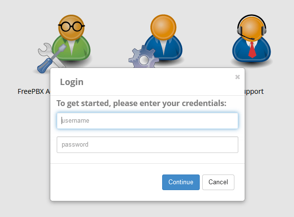
FreePBX is a powerful telephone PBX management platform that offers a range of functions, flexibility in customization, and rich integration
Who among us doesn’t like to use a free application, a free website or even a free cloud machine from